Metal Injection Molding (MIM) Process
Metal injection molding (MIM) offers a manufacturing capability for producing complex shapes in large quantities. The process utilizes fine metal powders (typically less than 20 micrometers) which are custom formulated with a binder (various thermoplastics, waxes, and other materials) into a feedstock which is granulated and then fed into a cavity (or multiple cavities) of a conventional injection molding machine. After the “green” component is removed, most of the binder is extracted by thermal or solvent processing and the rest is removed as the component is sintered (solid-state diffused) in a controlled-atmosphere furnace. The MIM process is very similar to plastic injection molding and high-pressure die casting, and it can produce much the same shapes and configuration features. However, it is limited to relatively small, highly complex parts that otherwise would require extensive finish machining or assembly operations if made fromany other metal-forming process.
The advantages of the metal injection molding process lie on its capability to produce mechanical properties, nearly equivalent to wrought materials, while being a net-shape process technology with good dimensional tolerance control. Metal injection molded parts offer a nearly unlimited shape and geometric-feature capability, with high production rates possible through the use of multi-cavity tooling.
Process Overview
- FeedstockMixing and Granulating
The first step in the MIM manufacturing process is the production of the feedstock that will be used. It begins with an extensive characterization of very fine elemental or pre-alloyed metal powders (generally less than 20 μm). In order to achieve the flow characteristics that will be required in the injection molding process, the powder is mixed together with thermoplastic polymers (known as the binder) in a hot state in order to form a mixture in which every metal particle is uniformly coated with the binder. Typically, binders comprise 40% by volume of the feedstock. Once cooled, this mixture is then granulated into pellets to form the feedstock for the injection molding machine.
- Molding
The next step is the molding of the part in a conventional injection molding machine. The feedstock pellets are gravity fed from a hopper into the machine’s barrel where heaters melt the binder, bringing the feedstock to the consistency of toothpaste. A reciprocating screw forces the material into a two-part mold through openings called gates. Once cooled, the part is ejected from the mold with its highly complex geometry fully formed. If necessary, additional design features not feasible during the molding process (undercuts or cross holes, for example) can be easily added at this stage by machining or another secondary operation.
- Binder Removal
The ejected as-molded part, known as a “green part”, is still composed of the same proportion of metal and polymer binder that made up the feedstock, and is approximately 20% larger in all its dimensions than the finished part will be. The next step is to remove most of the binder, leaving behind only enough to serve as a backbone holding the size and geometry of the part completely intact. This process, commonly referred to as “debinding”, may be performed chemically (catalytic debinding) or thermally, which in some cases may involve a solvent bath as the initial step. The choice of debinding method depends on the material being processed, required physical and metallurgical properties, and chemical composition. After debinding, the part is referred to as a “brown part”.
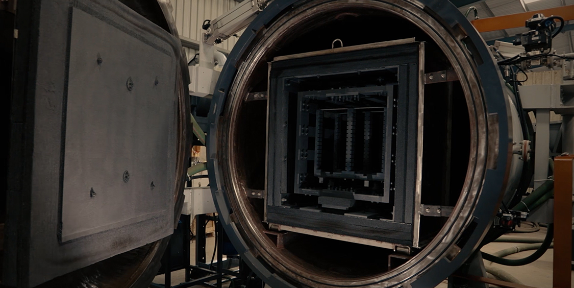
- Sintering
In this process, which is performed in the highly controlled atmosphere of either a batch furnace or a continuous furnace, the brown part is staged on a ceramic setter and is then subjected to a precisely monitored temperature profile that gradually increases to approximately 85% of the metal’s melting temperature. The remaining binder is removed in the early part of this cycle, followed by the elimination of pores and the fusing of the metal particles as the part shrinks isotopically to its design dimensions and transforms into a dense solid. The sintered density is approximately 98% of theoretical. The end result is a net-shape or near-net-shape metal component, with properties similar to those of one machined from bar stock. Of course, if necessary, post-sintering operations such as coining, machining, heat treating, coating, and others, may be performed on the part to achieve tighter tolerances or enhanced properties.
When to Use MIM?
MIM is an established, highly evolved metal-forming technology, producing intricate components that go into a great variety of end products in countless industries. But, as is true with all metal-forming technologies, MIM is not suited for every application, all the time.
To help you understand exactly where MIM emerges as the ideal fit for component fabrication, in this section we offer some general guidelines to use in assessing whether your part is a candidate for the metal injection molding process. You’ll also find some straightforward comparisons between MIM and alternative technologies that will provide further data for your assessment. Finally, we offer a comprehensive, though not exhaustive, listing of the range of materials that are being used in the production of MIM parts.
General Guidelines
What makes a particular component an ideal candidate for fabrication via MIM? We break down our guidelines into four basic areas: complexity, size, production volume, and final properties.
Complexity
MIM offers the same design freedom as plastic injection molding. The more geometrically complex a part is, the more solid the rationale for manufacturing it via the MIM process. Parts may include cross holes, angle holes, internal threads, irregular shapes, splines, undercuts, side holes or grooves, complex contours, orcantilevers.
Parts that would usually be made by assembling multiple components can be designed as a single MIM part. Some parts that could not be fabricated via any other process can be made through MIM. A Complexity that would be cost prohibitive to do via multiple machining operations or by casting and then finishing can be achieved cost effectively through MIM processing.
Size
In general, the weight range MIM parts tend to fall within is 0.1 to 250 grams, although above 100 grams the high cost of the extremely fine powders used in the process begins to neutralize MIM’s cost advantages, unless the complexity is extreme. The Parts should have wall thicknesses not less than .13 mm (.005 in.) and not more than 12.7 mm (.5 in.). Due to material flow limitations, the distance from gate to the farthest point on the part should be around four inches. MIM part tolerances are nominally ±0.3%–0.5%, although tighter tolerances can be achieved in some cases if deemed essential.
Production Volume
Medium to high volumes of 10,000 to 2,000,000 parts annually are typically needed in order to be able to amortize costs associated with tooling and start-up engineering. The best economic advantages are achieved at the highest quantities, due to the benefits of larger material purchases, multi-cavity tooling, and dedicated production units.
Final Properties
MIM fabrication is ideal where near-full density, high impact toughness, fracture toughness, and fatigue and corrosion resistance are required. And if non-standard material properties are required, these can be developed with new alloy systems.
MIM is appropriate for materials that are difficult to machine, materials with multi-phase microstructures, or high work-hardening materials. And it delivers a high-quality surface finish (32 rms or better) and cleaner feature detail than investment casting.
Technology Comparisons
There is a place for each of the traditional metal-forming processes: each has its own strong suits as well as its limitations. But wherever a component fabrication choice exists between MIM and one or more of the other processes, it pays to see how they stack up in a head-to-head comparison.
The following table shows how the four major processes fare in some of the more important parameters to consider.
| Parameter | MIM | PM | CNC Machining | Investment Casting |
| Density | 98% | 88% | 100% | 98% |
| Tensile Strength | High | Low | High | High |
| Elongation | High | Low | High | High |
| Hardness | High | Low | High | High |
| Complexity | High | Low | High | Medium |
| Surface Finish | High | Medium | High | Medium |
| Production Volumes | High | High | Low | Medium |
| Range of Materials | High | High | High | Medium-High |
| Cost | Medium | Low | High | Medium |
MIM vs. Conventional PM
- MIM can produce geometries that eliminate secondary operations
- MIM offers superior density, corrosion performance, strength, ductility
- MIM can combine two or more PM components into one, reducing part count
- MIM parts offers superior magnetic performance
MIM vs. Machining
- MIM designs save material and weight
- MIM provides cost savings through better material utilization—sprues and runners can be reground and reused as feedstock with no compromise to final properties
- Molding from a single tool eliminates multiple set-up operations
- Difficult-to-machine materials can be molded into a neat shape
MIM vs. Investment Casting
MIM can produce thinner wall sections, sharper cutting points
MIM produces a better surface finish
MIM is better for small-diameter blind and through holes
MIM greatly reduces requirements for finish machining
MIM produces high volumes of small components at a lower cost, faster lead times
Materials Range
The Metal Injection Molding industry can manufacture an extremely wide variety of metal alloy compositions for use in your application. The alloy families shown below make up a broad representation of the spectrum of alloys which can be/have been produced for various applications. If you do not see the exact alloy or alloy family shown on our extensive list in which you have interest, please contact your supplier in order to see if the alloy or a substitute alloy is available. Working closely with your supplier will enable you to find the best solution for your application.
The most common alloy families are:
Iron, low-alloy steels, stainless steels
Other alloys:
Aluminum alloys, bio-compatible alloys, carbides, ceramics, cobalt-based alloys, controlled-expansion alloys, copper and copper alloys, hard metals, heavy-metal alloys, magnetic alloys (soft and hard), nickel-based alloys, precious metals, reactive metals, shape-memory alloys, specialty alloys, titanium and titanium alloys, tool steels.